Parallel Controlled Power Supply
Parallel-controlled circuits operate as self-controlled, variable resistors, connected in parallel to the load impedance (parallel loads). They react extremely fast and also control immediately pulses and very short mains break-downs, resulting from strong loads. These devices are preferably used in TV receivers, which have a B-class operated audio output stage. Without any parallel control the picture width is influenced inconveniently by the rhythm of speech and music. However not only in TV receivers a parallel control circuit is advantageous, but there are also a lot of applications requiring such a design.
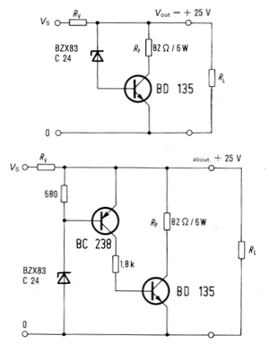
The parallel control circuit can also be described as a “z-diode booster”, which offers, however, the great advantage, that the power dissipation of the control transistor can be reduced to a quart of that of a z-diode representing the same function. Thus the collector resistor can take the total parallel-load when the transistor is switched on. Supposing that half of the voltage is available at the collector, only half of the current flows through the transistor, power dissipation of which is only a quart of the total power consumption of the parallel load. The circuits 1 and 2 are proportioned for a parallel load of </= 6 W. In many cases the former is sufficient. It is characterized by a remaining control voltage of < 250 mV. The circuit no. 2 consists of two stages and improves the voltage control to about 20 to 50 mV. The small elaborateness of only one transistor and one resistor is advantageous in many cases.
fig. 6.1 and 6.1.1

The circuits of fig. 6.1 and 6.1.1 are designed for fixed output voltages. The resistance of Rv is determined on the control range, on the value of the supply voltage and on its fluctuation. The maximum range of power control is determined by the resistance of Rp (control resistor).
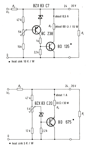
Fig. 6.1.2 and 6.1.3

The circuits of fig. 6.1.2 and 6.1.3 are dimensioned for a power of 15 or 30 W. The output voltage is adjustable in a range of 24 to 35 V, for instance. As it can be seen the circuit of fig. 6.1.3 employs only one transistor, the Darlington-transistor BD 675.
Power Supply Circuits – Parallel-Control Circuits
from Design Examples of Semiconductor Devices – 1974/75 of Siemens – The Silicon Pioneers


