Function Generator using the CA3140

Here is a complete project which will help in learning to apply the CA3140 in a small instrument that could be used in your test bench along with the oscilloscope. It is necessary to study the datasheet for understanding the device and this application with full details.
CA3140 4.5MHz, BiMOS Operational Amplifier with MOSFET Input/Bipolar Output

“A function generator having a wide tuning range is shown in Figure 10. The 1,000,000/1 adjustment range is accomplished by a single variable potentiometer or by an auxiliary sweeping signal. The CA3140 functions as a non-inverting readout amplifier of the triangular signal developed across the integrating capacitor network connected to the output of the CA3080A current source.”
Meter Driver and Buffer Amplifier
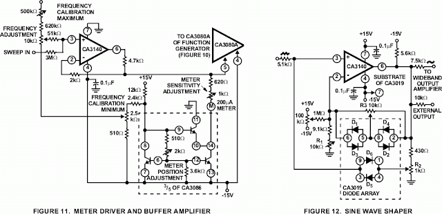
Figure 11 shows the CA3140 connected as a meter driver and buffer amplifier. Low driving impedance is required of the CA3080A current source to assure smooth operation of the Frequency Adjustment Control. This low-driving impedance requirement is easily met by using a CA3140 connected as a voltage follower. Moreover, a meter may be placed across the input to the CA3080A to give a logarithmic analog indication of the function generator’s frequency.
Sine Wave Shaper
The circuit shown in Figure 12 uses a CA3140 as a voltage follower in combination with diodes from the CA3019 Array to convert the triangular signal from the function generator to a sine-wave output signal having typically less than 2% THD.
Triangle and Square Wave Generation
Buffered triangular output signals are then applied to a second CA3080 functioning as a high speed hysteresis switch. Output from the switch is returned directly back to the input of the CA3080A current source, thereby, completing the positive feedback loop
The triangular output level is determined by the four 1N914 level limiting diodes of the second CA3080 and the resistor divider network connected to Terminal No. 2 (input) of the CA3080. These diodes establish the input trip level to this switching stage and, therefore, indirectly determine the amplitude of the output triangle.

Sweeping Generator
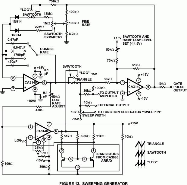
Figure 13 shows a sweeping generator. Three CA3140s are used in this circuit. One CA3140 is used as an integrator, a second device is used as a hysteresis switch that determines the starting and stopping points of the sweep. A third CA3140 is used as a logarithmic shaping network for the log function. Rates and slopes, as well as sawtooth, triangle, and logarithmic sweeps are generated by this circuit.

Wideband Output Amplifier
Figure 14 shows a high slew rate, wideband amplifier suitable for use as a 50? transmission line driver. This circuit, when used in conjunction with the function generator and sine wave shaper circuits shown in Figures 10 and 12 provides 18VP-P output open circuited, or 9VP-P output when terminated in 50?. The slew rate required of this amplifier is 28V/?s (18VP-P x ? x 0.5MHz).
Power Supply for Project
Use a good step-down transformer to isolate the mains supply and reduce the AC voltage. Rectify with a diode bridge to get DC, filter the DC with large electrolytic capacitors. Then implement this Dual Power Supply circuit along with LM7815 and LM7915 – Dual Polarity Power Supply


