Production Notes – Prototype Fabrication – 03
Prototype Fabrication and Pilot Production are the first stages of a design concept taking a real tangible form. The transition from R&D to Manufacturing Engineering happens here.
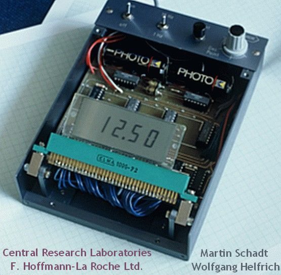
Early prototype of an alpha-numeric LCD based on the twisted nematic field-effect as realized in the laboratories of the Central Research Laboratories of F. Hoffmann-La Roche Ltd. by Martin Schadt and Wolfgang Helfrich, photo by courtesy of M. Schadt.
Sometimes a component can be defective, may not be what it is labeled or may be of a wrong value. In manufacturing 100% incoming inspection of components can catch these errors, Before Assembly of prototypes just test all passive and active components with a DMM and put all ICs in bases, then troubleshooting is easy.
- When you make your prototype check diode and el-cap polarity, check pin 1 of chips and connectors, resistor values, dry solder and loose contacts, hairline cuts or shorts, e-b-c etc. of Transistors, FETs and thyristors.
- Observe color code in wires. positive is red and negative is black and green is earth.
- When you are soldering or cutting leads, room should have cross ventilation, protective glasses for eyes and a good stand.
- When using a sharp blade the cutting stroke must move away from you and make sure nobody is close, Wear protective or even plain glasses, If you use a blade with the stroke moving towards your body it will cut badly.
- Power tools and machinery must be used only after exhaustive training and with safety precautions. The power tools used carelessly and wrongly can cause an injury which will last a lifetime or may even handicap you.
- Have a lathe lamp or table lamp with a 40W edison-filament lamp (ordinary bulb) on your workbench.
- Have an antistatic mat on the work or test table, if you cannot afford or get it then get a large aluminum sheet, laminate it with an insulating polycarbonate sheet and earth the metal plate with two 1M resistors in series.
- Use thin multi strand teflon wires for your jumpers within a PCB, these are not damaged by your iron too.
- Silicone shrink sleeves can withstand high temperature and use this in your work to make it safer and neat.
- When you make a connection with a wire you need mechanical strain relief or on use connection will open.
Soldering and Desoldering Tips
Use the soldering iron as a heat transfer tool, heat the junction of the lead of the component and the copper pad on pcb then touch the hot junction with a flux cored soldering lead wire, it should melt and form a concave shining joint.
If air bubbles are formed or you see dull convex joints, then it means you have a dry solder and bad contact. Leads of old components due to exposure to moisture, brine or sunshine will corrode, store them well cool-dry-clean-air. Anyway scratch them with a blade and solder them with extra flux.
When you are desoldering a double sided pcb, use a desoldering pump or desoldering wick. Heat a joint to be desoldered and then quickly tap it hard on the table, the molten lead will fall off.
delabs Notes from 90s
Read More
Soldering is to electronics what stitching is to clothes. If you are good at soldering then you have come half the way of mastering robot building. The only way you can achieve this is through ‘Practice’ alone. Remember, soldering is an ART and not a mere technique.