Design Notes – Schematic and PCB – 04
PCB Thermal Design Care for Analog Circuit Stability – If you have a hot power chip near a DC analog circuit, the values will drift, take time to stabilize, this happens even if you use 1% MFR 100ppm. The impact is more if the heatsink is not used and vents and coolers are absent,
So in a PCB keep distance between heating power circuits and sensitive analog circuits, some times PCB tracks will carry heat to the Analog area, Hence keep sensitive analog circuits as plugin modules.
When you make a PCB try to orient all ICs in one direction, so also all diode and cap polarities, then it is easy to populate the parts, easy to verify and troubleshoot for production and testing.
High Frequency and RF Design of PCB
- Sharp bends in PCB tracks or wires will radiate away the RF energy, so do not have hairpin bends.
- RF or near RF multilayer PCB have 2 layers as ground plane and tracks in the layer in between, Faraday cage.
- Electronic RF Product or System Design like Communication Products.. Important rule “the first rule of connectors is that the best connector is no connector at all…”. In RF the connectors and their placement needs extra care. At a frequency of 1 GHz, a short PCB track can become an Antenna !
Schematic Design Basics
- When we draw circuits we have to keep in mind the readability, the circuit should be laid out, according to the signal flow, the input output ports shown in the periphery of circuit.
- Drawing a neat circuit diagram will ensure a better design, lesser parts means greater reliability, simple solutions.
A well-drawn schematic makes it easy to understand how a circuit works and aids in troubleshooting; a poor schematic only creates confusion.
Product Design Mockup and Prototypes
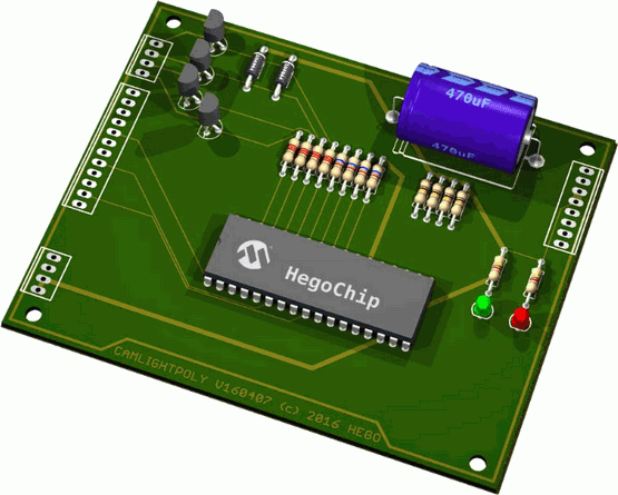
- Make a 3D mockup of the final product, both the box and the PCB with components before PCB done.
- The product with the PCbs, transformer and other panel components should fit in the box it was intended for, or the cabinet that was designed for the Product. To make sure make a Mock-up Product – 3D and display. Even if you have all documents and drawings in place.
- Make sure of IC pin numbers, size and packages and indicate in circuit like 40 pin dip before going to PCB. Also check every EDA symbol in your software with the company datasheet to make double sure.
- Do not mix mechanical and electrical connections, these leads to failures and frequent need of repairs and service. this is a rule, more so for power connectors.
- Strain relief prevents mechanical stress from reaching the connector joints/spring metal. The wire terminations are also cushioned by strain relief.
- The PCB and Product Engineering should ensure that the mechanical stress or load is not a job/function/role of the connector. At higher currents a small contact resistance can generate a lot of heat, worsening the contact further, similar to thermal runaway of Power Transistors.
- When using a double or multi layer pcb make one layer a ground plane, all decoupling caps ground linked to it.
- Reinforce copper tracks on PCB with a copper wire when it needs to carry more current, tinning may improve a bit.